How to Control Your CO2 in XPS Production Line
Table of Contents
What you will learn inside this guide
- Flow Chart of CO2 Handling System
- Keep the CO2 at a Certain Temperature
- More CO2 Control in XPS Production
Complete Guide
It is well known that CO2 is the most challengeable blowing agent to handle during the physical foam extrusion process. It is for reasons. For example, the supercritical point, touchy dry ice, and its density vary apparently when circumstance temperature changes etc. For end customers, knowing this information would not get you anywhere. You still need reliable design to warranty the productivity of your production line. I am not going to tell you many theories or terminologies. I just want to share our practical know-how of handling CO2 in XPS production.
To better understand the tricks at each unit of the whole system, let’s start from explanation of our flow chart. The following chart is not the real PID, it is just a sketch which will help you understand the way how we control the CO2. The actual PID is much more complicate than this which involves tens of valves and some other accessories.

Flow chart of CO2 handling system
Normally industrial use CO2 is delivered by truck that carries tens of tons of liquid CO2. And the CO2 will be stored in a big vacuum insulated tank which is generally 25 tons approximately. The temperature of CO2 inside of the tank is about minus 20 degree Celsius, and the pressure is between 1.6-2.0Mpa. When the environment temperature change causes the pressure rise, the tank will give off CO2 to cool down itself.
As you know that liquid is much easier to hand than gas. So we are gonna manage to keep CO2 in the state of liquid during the whole process. Because the CO2 is very liable to vaporize due to its high vapor pressure, so we have to strike the balance between pressure and temperature. This is the foundation of how our system works.
We employed a booster pump that will transport the liquid CO2 from CO2 tank to middle tank whose wall was jacketed design, by which the temperature of the middle tank could be controlled by water temperature controller. One tip I have to bring it up here is that the distance between CO2 tank and middle tank has to be as near as possible. Due to the CO2 has the propensity of vaporizing so that the longer distance, the more risky to vaporize.
To do so, the booster pump is recommended to put under the CO2 tank. Even so, the vaporizing still happens occasionally. When the booster pump is not able to pump the CO2 properly, vaporizing probably happened. The discharge valve is designed for this situation, so open it and let out the vaporized CO2 in order to cool down the temperature of the head of the booster pump.
This process has to be done very carefully, because if the discharge valve is opened too much, the CO2 is liable to become dry ice which will block the pipe, and it will take very long time to melt away. To avoid this circumstance happen, the capacity of the booster pump should be ten times bigger than metering pump so that the booster pump does not have to work all the time, only works periodically.
Besides, longer discharge pipe is advised which can prevent the inlet pipe of booster pump from freezing by dry ice. In addition, the insulated piping of the whole system will contribute to the consistence of CO2 transport, also it can save energy.
The purpose of middle tank is to keep the CO2 at a certain temperature (around 25 degree Celsius) in order to maintain the pressure of the whole system is stable and high enough (6.5-7Mpa). These two premises ensure the constant physical property of CO2 and it gets CO2 primed for precise metering into twin screw extruder. As I mentioned before, the density of CO2 varies when temperature changes.
The highest level alarm of CO2 in the middle tank should be no more than 70% of the total volume of the middle tank in case of any incident happened, the power cut in the summer in some hot region, which may cause circumstance temperature of middle tank goes high, then the CO2 may become supercritical state whose behavior is more difficult to control and predict. As a result the volume of CO2 will be expanded greatly. If the free space is not enough, it may get the middle tank in some danger.
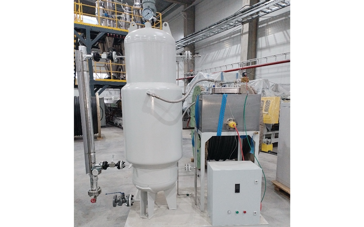
middle tank and temperature control vessel
Before CO2 goes into middle tank, it will be warmed up to ensure the temperature of CO2 in the middle tank at a certain degree as it is intended. Normally it is 25 degree Celsius. At this temperature the pressure of middle tank is about 6.5Mpa.
Why is it to be set at this temperature? In many countries, 10Mpa is a watershed to separate high pressure vessel and super high pressure vessel. The latter requires complicated certificates and more expensive. So 7Mpa is safe for high pressure vessel. After going through the middle tank, the OO2 goes into another cooling vessel which will bring the temperature of CO2 down to 10 ten degree Celsius. Now the circumstance of 6.5Mpa and 10 degree Celsius make the CO2 in pure liquid. And the more liquid, the easier to dose. CO2 in this state can be metered into the primary extruder (twin screw extruder) readily. One thing has to be addressed is that the pump head has to be cooled by a chiller. When the pump heads are working, it will generate some heat which can make liquid CO2 vaporized that will trouble the process.
When all above mentioned points have been taken care of, it still cannot guarantee that the CO2 can be handled correctly. If any section of piping traps vaporized CO2, this system would not work properly. One thing you need to do is to open the discharge valve with great attention to avoid big dry ice occurs. The discharge valve before injection valve is strongly recommended. When you see the white smoke (small particles of dry ice) comes out, there you go, just close the valve. Now the CO2 is working out.
This is our way to control CO2 system. This is the combination of considering China-made, economic, reliability and practical. There are some other ways also can control CO2 very well. For example, LINDE PRESUS and DSD package can handle the CO2 precisely as well. Just our system is based on the condition of made-in-China. According to our long time expertise, China-made piston pumps are no problem at all in handling CO2. The disadvantage of piston pump is that the risk of leakage of China-made is bigger than membrane pump over time. But CO2 is nontoxic and nonflammable; it doesn’t make sense to worry about this risk. Moreover, the sealing stuff is very cheap and accessible. Changing sealing stuff can be put as a routine into the maintenance work. However, the flammable blowing agent like HFC152a, ethanol, DME, Isobutene etc. is better handled by membrane pump.
Our foam extrusion lab is using another system which can handle small quantity CO2 very well. But it is only for lab use now. This system cools the CO2 down to minus 20 degree Celsius to make the CO2 in the state of pure liquid with a little pressure. Normally this system works with a CO2 cylinder which just contains tens of kilos of CO2. It is relatively inexpensive and easy to operate.
All in all, it is better to maintain the CO2 in the state of pure liquid during the entire handling process. As to the so-called supercritical CO2 foam XPS production line, it is because the CO2 becomes supercritical state when it is injected into the barrel where the temperature is around 200 degree Celsius. The name has nothing to do with the handling process.