
When selecting an XPS production line, investors usually start with two questions: How much can it produce per hour, and how much does the complete line cost?
Useful answers require a clear understanding of the boards you plan to produce, the expected sales volume, and the conditions available at your factory. Two lines both rated at 600 kg/h may deliver different sustained outputs of qualified boards when thickness, density, raw materials, or blowing agents differ. Likewise, a price gap between two quotations may reflect differences in the scope of supply or the level of automation.
An XPS production line is an integrated, continuous manufacturing system used to produce extruded polystyrene (XPS) foam boards from metered raw materials through melt compounding, blowing-agent injection, melt cooling, extrusion forming, and downstream processing. For buyers, the key to line selection is matching product requirements, output targets, and factory conditions.
USEON recommends starting with the target product, then defining the required capacity, process configuration, investment budget, and factory conditions in sequence. These requirements should then be translated into the technical proposal and acceptance criteria.
1. Start by Defining the Boards You Will Produce
Before speaking with an equipment supplier, prepare a target product list. In addition to thickness, width, and density, include the intended applications, performance requirements, and estimated share of sales for each product.
| Item to Define | How It Affects Line Selection |
|---|---|
| Main applications and customer requirements | Wall or roof insulation, underfloor-heating insulation, load-bearing insulation, and sandwich-panel core materials place different priorities on performance and downstream processing. |
| Common thicknesses, widths, and share of each specification | Affects the matching of line model, die, sizing system, and downstream processing capacity. |
| Density and performance targets | Provides the basis for raw-material, blowing-agent, and process decisions. Requirements for thermal conductivity, compressive strength, dimensional stability, and other properties should be specified together. |
| Surface and edge profiles | Determines whether skin removal, grooving, embossing, shiplap edges, or tongue-and-groove profiling is required. |
| Frequency of specification changes | Affects production scheduling, adjustment workload, and changeover losses. |
Line selection should focus first on the products expected to account for most sales. Special specifications produced only occasionally can be evaluated separately, but a line should not be judged suitable for routine production solely because it can cover the maximum stated specification range.
Thin and thick boards place different demands on the complete line. At the same density, width, and output by weight of qualified finished boards, thinner boards require a higher line speed. For example, when thickness decreases from 50 mm to 25 mm, the required line speed doubles based on geometry. A thin-board project must therefore evaluate sizing, haul-off, cutting, and stacking capacity together with extrusion output.
For thick-board production, greater attention is required to the coordination of foaming, cooling, and sizing, as well as quality uniformity through the thickness and dimensional stability. Even if a line can produce a specified maximum thickness, its stable output and finished-board performance at that thickness still need to be verified.
For projects producing core materials in-house for sandwich or coated panels, the downstream lamination process may impose specific requirements on the surface, thickness tolerance, and bonding. Equipment for processes such as steel-sheet lamination or cement-based coating should be treated as a separate operation, with its scope of supply confirmed independently.
2. Convert Sales Targets into Required Capacity
XPS boards are commonly sold by cubic meter or square meter, while production-line output is generally stated in kg/h. Before comparing models, use a consistent unit basis and distinguish extrusion output from the final output of qualified finished boards.
Work Back from Monthly Demand to Hourly Output
A simplified formula for preliminary planning is:
Required extrusion output (kg/h) ≈ Monthly demand for qualified boards (m³) × Finished-board density (kg/m³) ÷ Monthly feeding and extrusion time (h) ÷ Yield of qualified finished boards.
Consider an XPS board with a target finished density of 30 kg/m³. Assume that 9,000 m³ of qualified boards must be supplied each month, with 600 hours of feeding and extrusion time per month and an estimated qualified-finished-board yield of 85%:
9,000 × 30 ÷ 600 ÷ 0.85 ≈ 529 kg/h.
Under these conditions, the required extrusion output is approximately 529 kg/h. Final model selection should also account for operating performance on the main specifications, capacity margin, and future expansion plans.
The 30 kg/m³ figure is the target finished-board density used in this example. For your own project, use the actual density required for the target product and determine operating time and yield from the production plan. Density should be specified together with performance requirements such as thermal conductivity, compressive strength, and dimensional stability.
Use a consistent basis throughout the calculation. Deduct planned maintenance, shutdown and heat-up periods, and other non-feeding time from available production time. Material extruded during start-up or specification changes but not meeting quality requirements may be included in the yield calculation, so the same loss is not deducted twice. If the sales target is stated in square meters, multiply it by board thickness to convert it to cubic meters. Calculate each product specification separately and then add the results.
Trim waste can be 100% recycled, but the material cut off in the current production cycle has still not become a saleable finished product. Recycling reduces raw-material waste; it does not justify calculating the yield of qualified finished boards as 100%.
Select a Line Model That Matches the Output Target
The USEON ECOFEL series of XPS production lines covers a range of capacity requirements and can be configured for different board specifications, raw materials, and blowing-agent systems. Key selection data for the main models are shown below:
| Line Model | Reference Output (kg/h) | Reference Transformer Capacity (kVA) |
|---|---|---|
| TDS75–TDD150 | 200–450 | 300 |
| TDS75–TDD200 | 400–600 | 400 |
| TDS95–TDD250 | 600–1,000 | 600 |
| TDS110–TDD300 | 800–1,200 | 800 |
| TDS135–TDD400 | 1,500–2,000 | 1000 |
| TDS135–TDD500 | 2,000–3,000 | 1,200 |
Note: Actual output and operating ranges depend on board specifications, formulation, and equipment configuration and are subject to the project-specific technical proposal. Transformer capacity must be calculated according to the complete line configuration and the loads of other equipment in the factory.
For the 529 kg/h requirement calculated above, a 600 kg/h-class solution is already close to the required output, so the model should not be selected from the maximum output figure alone. If the main specifications cannot be maintained at that output over long runs, or if frequent product changeovers are required, actual deliveries may fall short. The next larger solution can provide capacity margin, but initial sales volume, inventory, working-capital requirements, and suitability at lower operating rates must also be evaluated. If the line operates for extended periods below 70% of its rated maximum output, its energy consumption per cubic meter will be more than 15% higher than that of a lower-capacity model producing the same output. It is also important to note that XPS board density and output are inversely related. For example, the output of the same line when producing 50 kg/m³ boards is only about 75% of its output when producing 30 kg/m³ boards. Output falls noticeably when board density exceeds 32 kg/m³. These figures can also be affected by the altitude of the installation site.
Capacity should be selected on the basis of the sustained output of qualified finished boards in the main product specifications.
Capacity planning for an XPS project should also account for the way continuous production will be organized. If initial demand is low, compare the economics of concentrated continuous production with those of choosing a smaller line, while considering inventory, delivery, and working-capital requirements. Any expansion plan should be supported by a clearly defined sales-growth forecast.
3. Define the Configuration Around Raw Materials, Foaming Process, and Finished-Product Requirements
The configuration should be designed to produce the target products reliably. Raw materials, formulation, specification changeovers, and downstream processing requirements collectively determine the appropriate feeding, extrusion, cooling, and downstream systems.
Raw Materials and Feeding: Specify What You Plan to Use
Raw-material information should include, at a minimum, the PS resin, flame-retardant system, other additives, and the source, form, and planned addition ratio of recycled material.
The phrase “50% recycled material” can describe very different processing conditions. Clean in-house trim and externally sourced recycled PS may differ in material form, bulk density, contamination, and batch-to-batch consistency, all of which affect conveying, metering, and subsequent processing. When selecting a line, provide the source and quality information for the recycled material and, where necessary, samples. Output with 100% recycled material is typically 10%-15% higher than with 100% virgin material.
The number of feeding components should correspond to the materials that require independent control in the formulation. If a low-dose additive requires frequent adjustment, independent metering provides the necessary formulation control. If a material tends to bridge, reliable discharge from the hopper and stable conveying must also be addressed. Simply adding more feeding components cannot replace proper control of the metering range, material flow characteristics, and refill fluctuations. We generally recommend no fewer than 6 loss-in-weight feeders.
Extrusion and Cooling: Evaluate the System as a Whole
In a tandem arrangement combining a co-rotating twin-screw extruder with a cooling single-screw extruder, the first stage is mainly responsible for plasticizing, dispersion, and mixing, while the second stage provides further cooling and melt transfer. The key question is whether both extrusion stages and the foaming process can operate together at the target output.
As extrusion output increases, cooling capacity must increase accordingly. A higher melt throughput requires the cooling system to reduce temperature under the corresponding operating conditions while maintaining the temperature and pressure needed for stable foaming. Adequate plasticizing capacity in the main extruder does not mean the complete line can produce qualified boards steadily at the same output.
Factories in high ambient temperatures, or those with limited existing cooling facilities, should provide summer ambient conditions and available cooling-water conditions during the proposal stage. Designing the cooling system for the actual operating environment helps avoid additional modifications after installation.
Main motor power, screw diameter, and L/D ratio are useful comparison points, but the final judgment should still be based on operating performance with the target formulation.
As a rule of thumb for a properly matched line, output in kg/h should generally be 4-5 times the twin-screw extruder’s main motor rating in kW. For example, if the twin-screw main motor is rated at 200 kW, the line’s nominal output should be 800-1,000 kg/hr. A twin-screw speed above 300 rpm should be avoided, and larger machines should use lower screw speeds. Flame retardants currently used for XPS have limited resistance to thermal decomposition. The process must therefore achieve sufficient dispersion while minimizing shear heat during extrusion. Excessive screw speed inevitably generates excessive shear heat, which can reduce flame-retardant performance or require a higher flame-retardant dosage, increasing production cost.
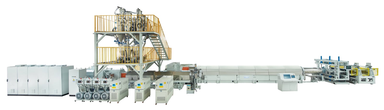
Blowing Agents: Confirm the Formulation Route and Supply Conditions Early
The blowing-agent system should be determined before finalizing the main extruder and injection system. When selecting a blowing-agent combination, consider locally applicable requirements, supply stability, target board performance, and process compatibility. A lower-priced medium may not reduce total project cost if it cannot be sourced reliably or requires additional storage and transfer facilities. For example, although HFO can provide good thermal-insulation performance, its supply stability and high price must also be considered.
When discussing CO₂ and other co-blowing-agent systems, specify the actual media, form of supply, and formulation limits. A line’s ability to use one blowing agent does not mean that every combination will achieve the same output and product performance.
Storage, transfer, ventilation, and the corresponding safety facilities should be confirmed as part of the same proposal. Ask the supplier in advance about any equipment modifications that may be required if the blowing-agent system is changed later.
Downstream Processing and Automation: Configure for Finished-Product Delivery Requirements
Whether downstream processing should be arranged online or offline depends on the product mix and production cycle. For long, continuous runs of similar boards, online processing reduces handling and intermediate storage. If only a small share of products requires a special surface or edge profile, offline processing allows that operation to be scheduled independently, but requires additional transfer space and handling. USEON can configure sizing, cutting, surface treatment, packaging, and loading and unloading systems accordingly.
| Configuration Item | Questions the Buyer Should Confirm |
|---|---|
| Sizing, haul-off, and cutting | Can the equipment handle the line speeds, dimensional tolerances, and cut quality required for the main specifications? |
| Surface treatment, skin removal, grooving, and edge profiling | Which products require these processes? How will online or offline operation affect changeovers and material flow? |
| Stacking and packaging | Can the equipment keep pace with production? After automation, which positions are still required on each shift? |
| Waste recycling | Can the system handle start-up waste, edge trim, and downstream-processing waste? Is recycling capacity sufficient? |
| Centralized control | Does the system provide the required recipe management, trend recording, alarms, interlocks, and remote support? Must the line interface with your group headquarters’ SCADA/MES system? |
The XPS waste recycling system should be planned together with the production line, with clear routes for waste collection, conveying, processing, and reuse. USEON can configure a recycling solution according to the form and volume of waste generated and its intended subsequent use.
How a Practical Configuration Comes Together
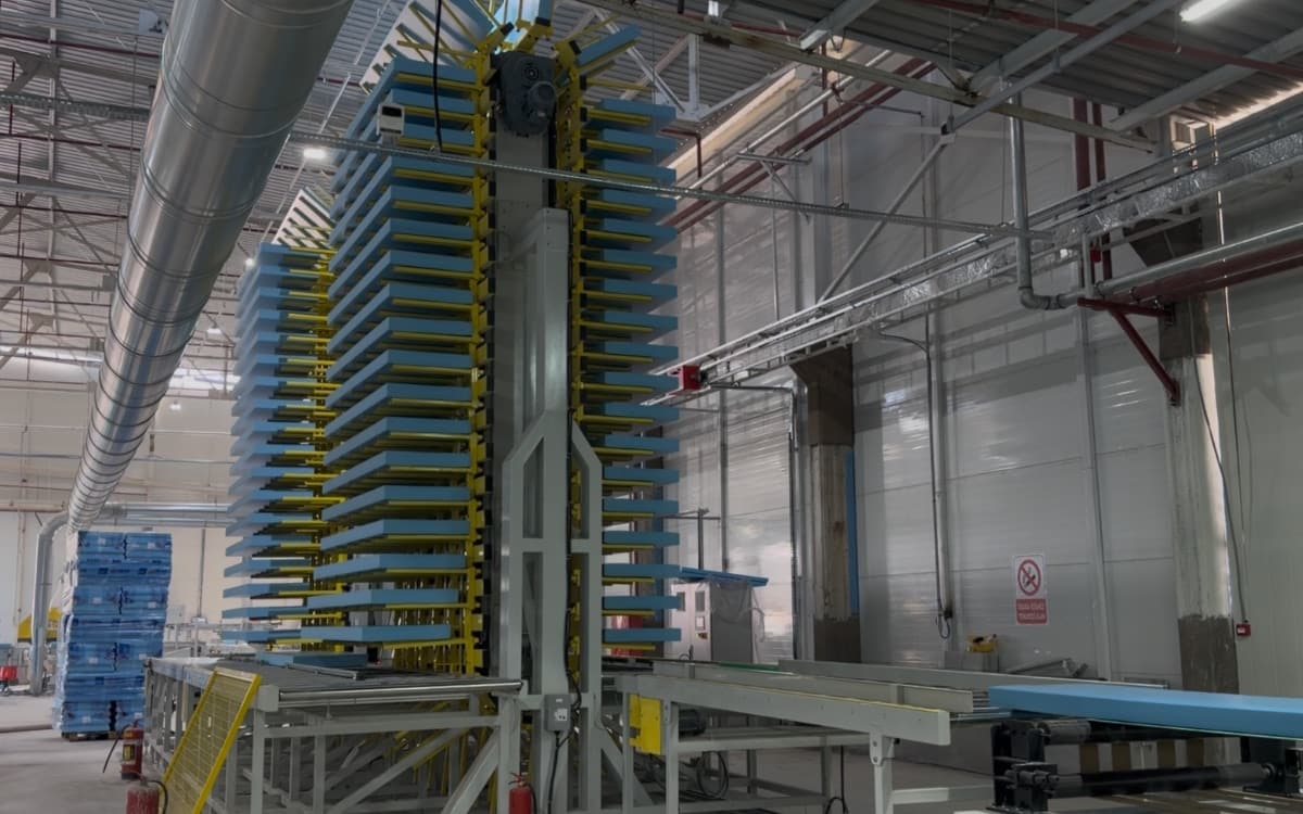
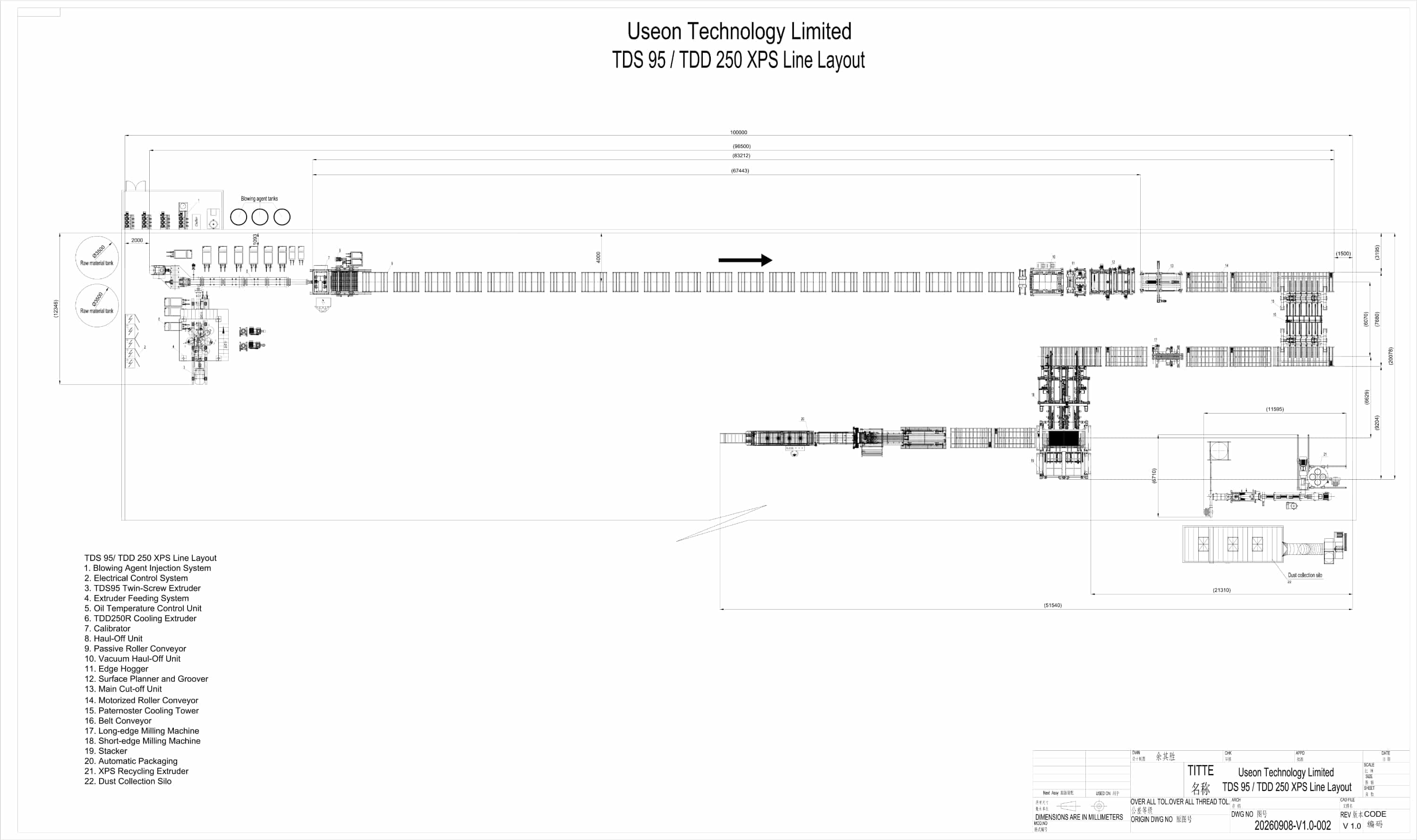
In one USEON TDS95–TDD250 XPS project, the line was designed for an output of 600–1,000 kg/h. A TDS95 twin-screw extruder plasticizes GPPS and recycled PS, while a TDD250 single-screw extruder provides cooling. The line also includes 8-component loss-in-weight feeding, multi-roll haul-off, precision milling, and a central dust-collection system.
This example integrates raw-material handling, extrusion cooling, and downstream processing within one solution. For a new project, the number of feeding components and the downstream equipment should still be determined by the project’s own product requirements.
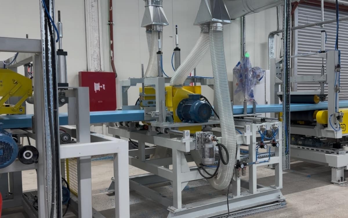
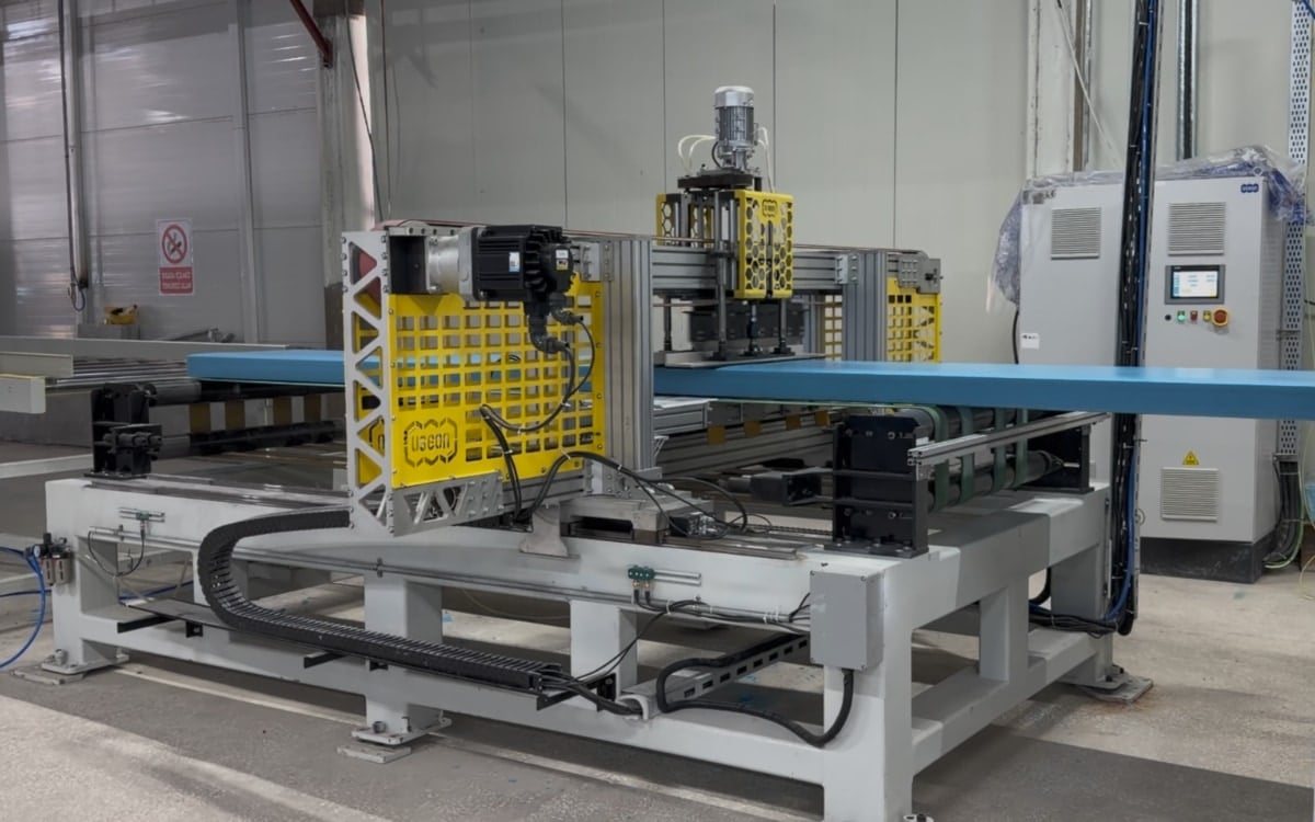
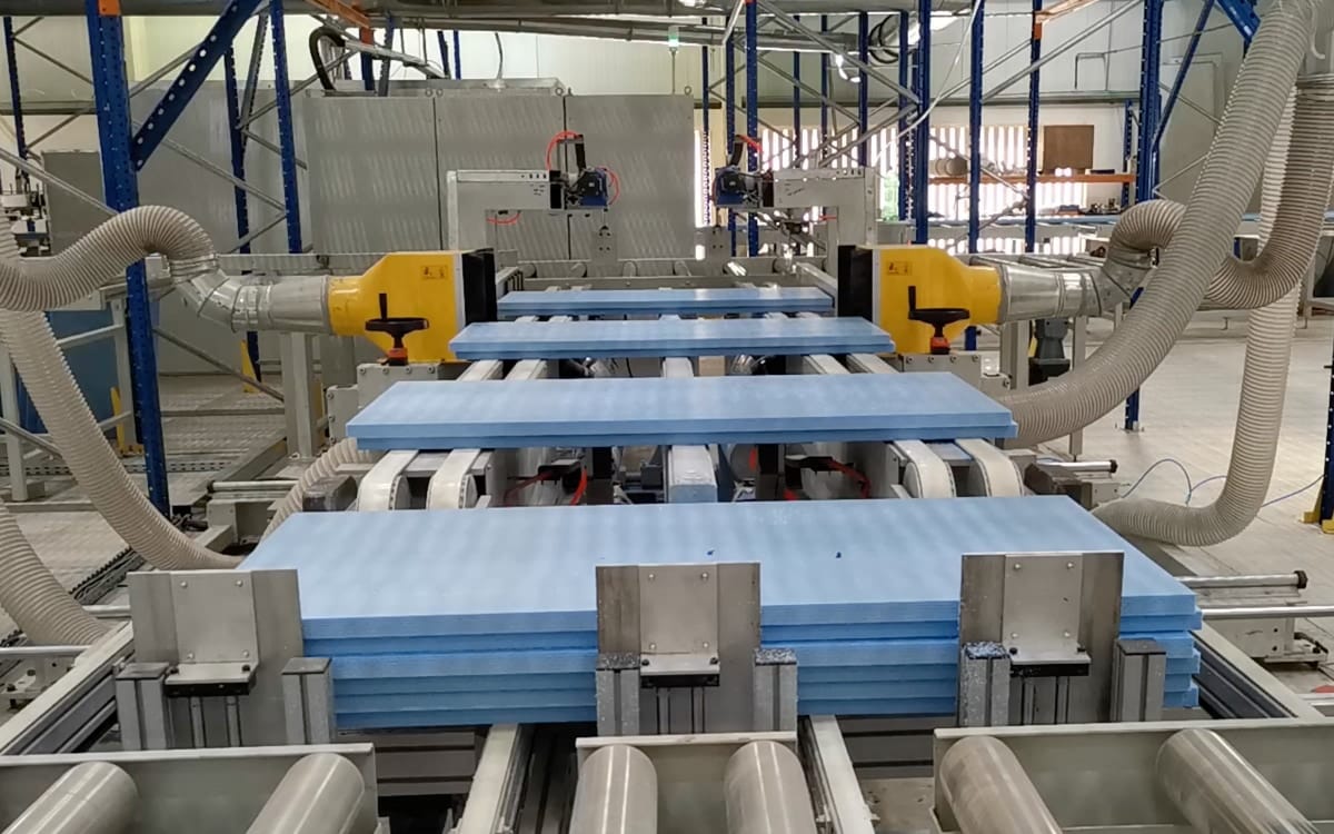
For an expansion at an existing factory, identify the actual bottleneck first. If packaging and stacking can no longer keep pace with production, increasing extrusion capacity alone will not produce more deliverable finished products. Evaluate targeted upgrades before deciding whether to add a complete new line.
4. Evaluate Equipment Budget and Production Cost Together
The budget for an XPS project should cover the full process from equipment procurement to stable commercial supply. Comparing prices is meaningful only when quotations have similar scopes of supply and performance conditions.
What Costs Should Be Budgeted for Project Start-Up?
| Budget Category | Items to Include |
|---|---|
| Production equipment | Main extruders, feeding, injection, die, sizing and cutting, downstream processing, recycling, optional automation, and necessary quality-control equipment. |
| Factory and utilities | Civil works or modifications, power distribution, cooling, compressed air, raw-material and finished-product storage, ventilation, and necessary safety facilities. |
| Delivery and start-up | Freight, insurance, applicable duties and taxes, unloading and lifting, installation and commissioning, training, and the initial spare-parts package. |
| Start-up and working capital | Trial materials, initial production losses, raw-material inventory, personnel costs, and capital tied up in customer payment terms. Normally, at least enough material for 10-15 days of continuous production should be prepared. |
Before comparing equipment prices, align the scope of delivery. Whether cooling, automatic packaging, and waste recycling equipment are included directly affects the start-up investment. Each quotation should identify every item as “included,” “optional,” or “by buyer,” and should define responsibility for equipment connections and installation. This prevents a narrower scope of supply from being mistaken for a lower total project cost.
Before product specifications, the blowing-agent route, and the scope of supply are defined, a single headline price for the entire line offers little value for investment decisions. A useful budgetary quotation should also state the design basis, equipment list, exclusions, and validity period.
Compare Operating Costs Using Qualified-Board Output
Prepare a cost sheet per cubic meter of qualified board. At a minimum, include raw materials and additives, blowing agents, electricity, labor, packaging, and maintenance. Add depreciation, financing, and factory costs as required.
Energy-consumption comparisons must use a clearly defined measurement boundary. Measuring only the main extruder will produce a different result from including cooling, recycling, compressed air, and downstream equipment. Competing solutions should also be compared under similar board specifications, density, formulation, and production load.
When comparing operating costs, focus on actual material consumption, complete-line power consumption, labor input, and specification-change losses per cubic meter of qualified board. Installed power in an equipment quotation describes the electrical configuration; actual electricity consumption must be measured under the agreed production conditions.
5. Verify Factory Space and Utilities Before Ordering
Confirming that the equipment physically fits inside the factory is only one part of layout planning. The movement of raw materials, production flow, recycling, temporary finished-product storage, and loading must also be workable.
The Factory Layout Should Cover the Complete Production Flow
Factory planning should begin by mapping the flow of materials and finished products before equipment positions are assigned. A floor plan showing the column grid, door openings, clear height, power-distribution locations, and logistics routes will help USEON develop a complete-line layout suited to the available space.
In addition to the line itself, allow for raw-material storage, waste recycling, finished-board cooling or conditioning, packaging, warehousing, and forklift access. Space for screw removal, die lifting, equipment disassembly, and maintenance should also be reserved.
Storage requirements for XPS boards should be planned by volume. Multiply the planned daily volume of finished boards by the inventory turnover period to estimate the board volume that must be accommodated. Then convert that volume into floor area based on stacking method, usable height, aisles, and management requirements. As output increases, temporary finished-product storage, packaging, and loading capacity must be evaluated at the same time.
Ask the Supplier for a Project-Specific Utility and Site Requirements Sheet
| Utility or Site Condition | Data or Boundaries to Define |
|---|---|
| Power | Voltage, frequency, total installed power, expected operating load, transformer selection basis, and the buyer’s auxiliary-equipment loads. |
| Cooling | Required flow for each circuit, inlet-water temperature, pressure, water quality, and design ambient conditions. |
| Compressed air | Operating pressure, air consumption, air quality, and points of use. |
| Blowing-agent supply | Media, form of supply, storage and transfer method, and interfaces between the equipment and factory utilities. |
| Installation and maintenance | Foundation and load-bearing requirements, lifting conditions, maintenance clearances, and responsibility for connection works. |
kW is a unit of power, while kVA is used for transformer capacity; the two cannot be treated as equivalent. Cooling-water and compressed-air pressure and flow must likewise be specified separately.
Factory dimensions and utility requirements should be based on the layout and utility requirements sheet for the selected configuration. For an existing factory, verify the remaining available capacity after other equipment is operating.
6. Compare Suppliers Using Operating Evidence and Acceptance Criteria
After completing a preliminary technical concept, provide every shortlisted supplier with the same product and project requirements sheet so that quotations and output commitments share a common basis for comparison.
Prioritize References Close to Your Target Operating Conditions
The value of a reference project depends on how closely it matches your own. Focus on operating results for similar thicknesses, densities, raw materials, blowing agents, and output levels, and ask what can be verified through a trial run or site visit.
Technical service should cover both equipment start-up and subsequent production. Responsibility for commissioning, operator and maintenance training, support for specification changeovers, spare-parts supply, and remote troubleshooting should all be defined during procurement. Reference projects help demonstrate the maturity of a solution, while a clearly defined service scope helps buyers assess the support available after start-up.
Convert Commitments into Verifiable Acceptance Items
| Acceptance Item | Conditions to Agree in Advance |
|---|---|
| Test product | Representative thickness, width, density, surface, and edge profile. |
| Raw materials and formulation | Resin, source and proportion of recycled material, flame-retardant system, and blowing-agent system. |
| Output and yield | Whether the figure refers to extrusion output or qualified finished-board output; calculation method, test duration, and treatment of waste. |
| Board quality | Applicable requirements for dimensional tolerance, density, thermal conductivity, compressive strength, and other properties, together with sampling and test conditions. |
| Energy consumption | Which equipment is included, how consumption is measured, and the corresponding production conditions. |
| Functions and delivery | The specific scope of safety interlocks, alarms, training, technical documentation, spare parts, and related items. |
For board properties that must be tested after a specified conditioning or aging period, define the sampling time, test method, and division of responsibility. Normal equipment operation and successful product-performance testing should be documented as separate verification records.
The conditions and scope for the factory acceptance test (FAT) and site acceptance at the buyer’s facility should be agreed separately. If the supplier cannot complete all foaming trials at its factory, the parties should identify in advance which items will be verified before shipment and which will be completed at the customer’s site, together with the procedure for handling deviations.
Every member of USEON’s expert team has more than 10 years of industry experience. We are ready to work with you to evaluate and define the solution best suited to your project.
Prepare These Seven Items Before Requesting a Quotation
You do not need to finalize every process detail before contacting an equipment supplier. A clear project requirements sheet is enough to begin a focused technical discussion:
- Project location and type: New factory, capacity expansion, or upgrade of an existing line.
- Target products: Applications, main specifications and their proportions, density, and performance requirements; include samples or customer specifications if available.
- Output target: Monthly or annual demand, unit of measurement, planned production time, and future expansion expectations.
- Raw-material plan: Sources, forms, quality information, and planned proportions of resin and recycled material.
- Blowing-agent conditions: Options already under consideration, local supply conditions, and applicable requirements at the project location.
- Factory and utilities: Floor plan, clear height, and existing power and cooling facilities.
- Budget and schedule: Whether the figure refers to the equipment budget or total project budget, preferred level of automation, and target start-up date.
If you are planning a new XPS project, a capacity expansion, or a line upgrade, send the information above to USEON. Our engineers can then discuss the line model, process configuration, scope of supply, and factory requirements with you and prepare a preliminary solution matched to your target products and output.

Vice President at USEON with experience in plastic extrusion machinery, research and development, polymer foam extrusion, international business development, and manufacturing.